
 Input modes
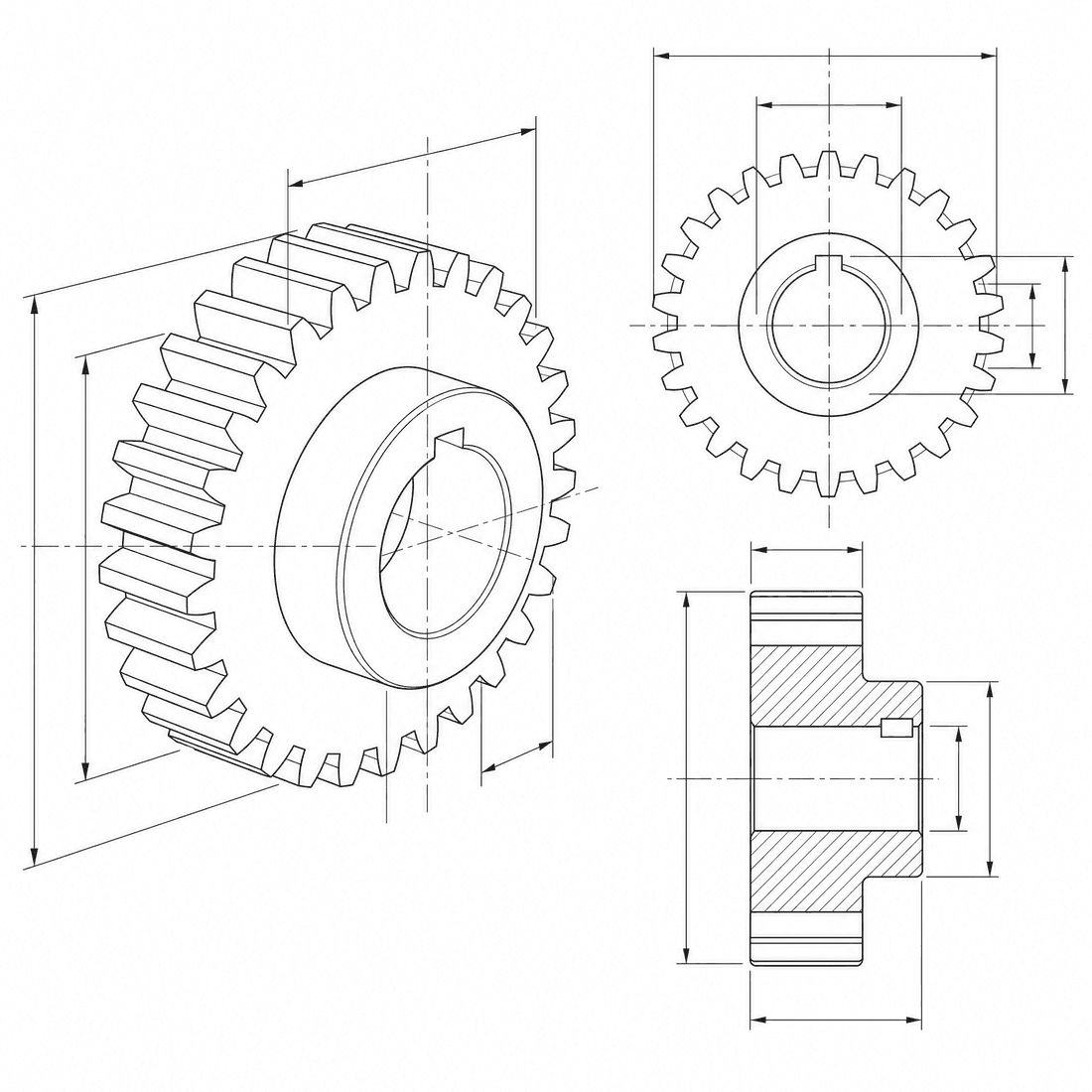
Spur gear
A 20-tooth spur gear with a center bore, keyway, and hub, drawn as a clean isometric CAD image
Prompt library
Every worked prompt written for a DrawCAD tool page or task kit, collected in one place. Copy one, swap in your own dimensions, and send it straight to the generator.
231 prompts · 5 categories · from 30 tool pages
Showing 231 of 231 prompts
Input modesA 20-tooth spur gear with a center bore, keyway, and hub, drawn as a clean isometric CAD image
 Input modes
An L-shaped aluminum mounting bracket with four bolt holes and rounded fillets, described in plain English
 Input modes
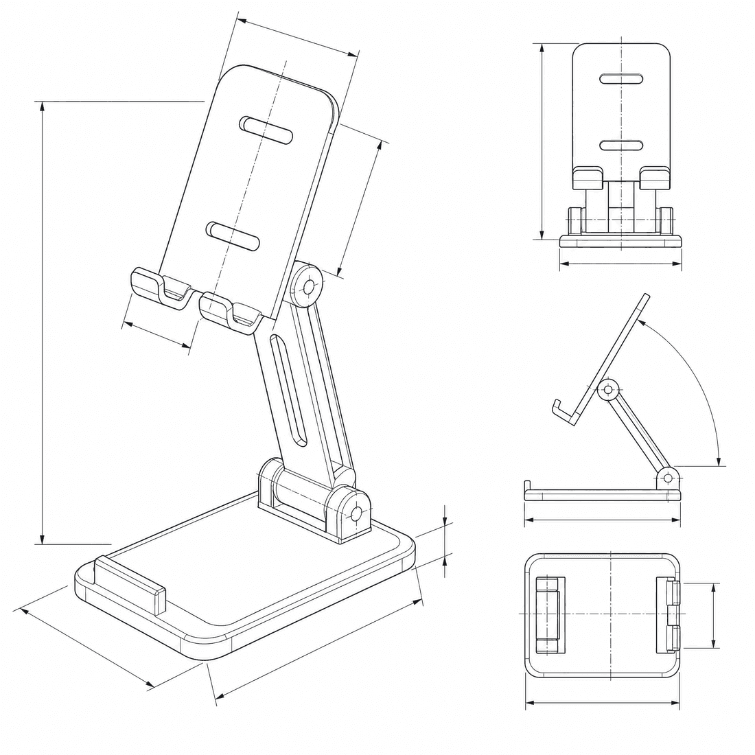
A foldable desk phone stand with an adjustable hinge, cable slot, and non-slip base
 Input modes
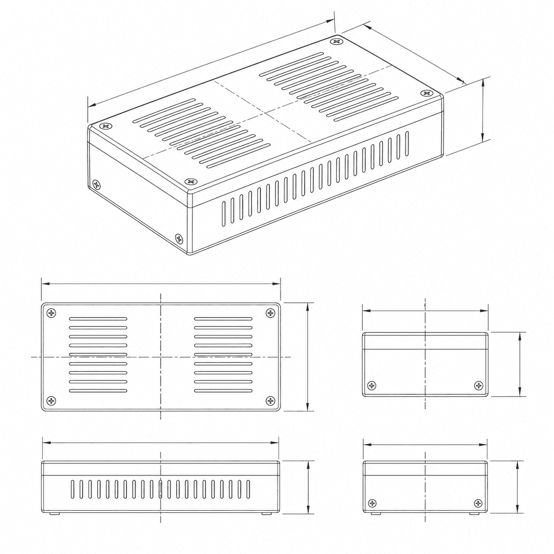
A small handheld electronics enclosure with a snap-fit lid, screw bosses, and side vent slots
Input modesClean this rough bracket sketch into a precise CAD-style technical drawing with mounting holes and dimensions
Input modesConvert this gear sketch into a clean CAD drawing with visible teeth, center bore, and dimension callouts
 Input modes
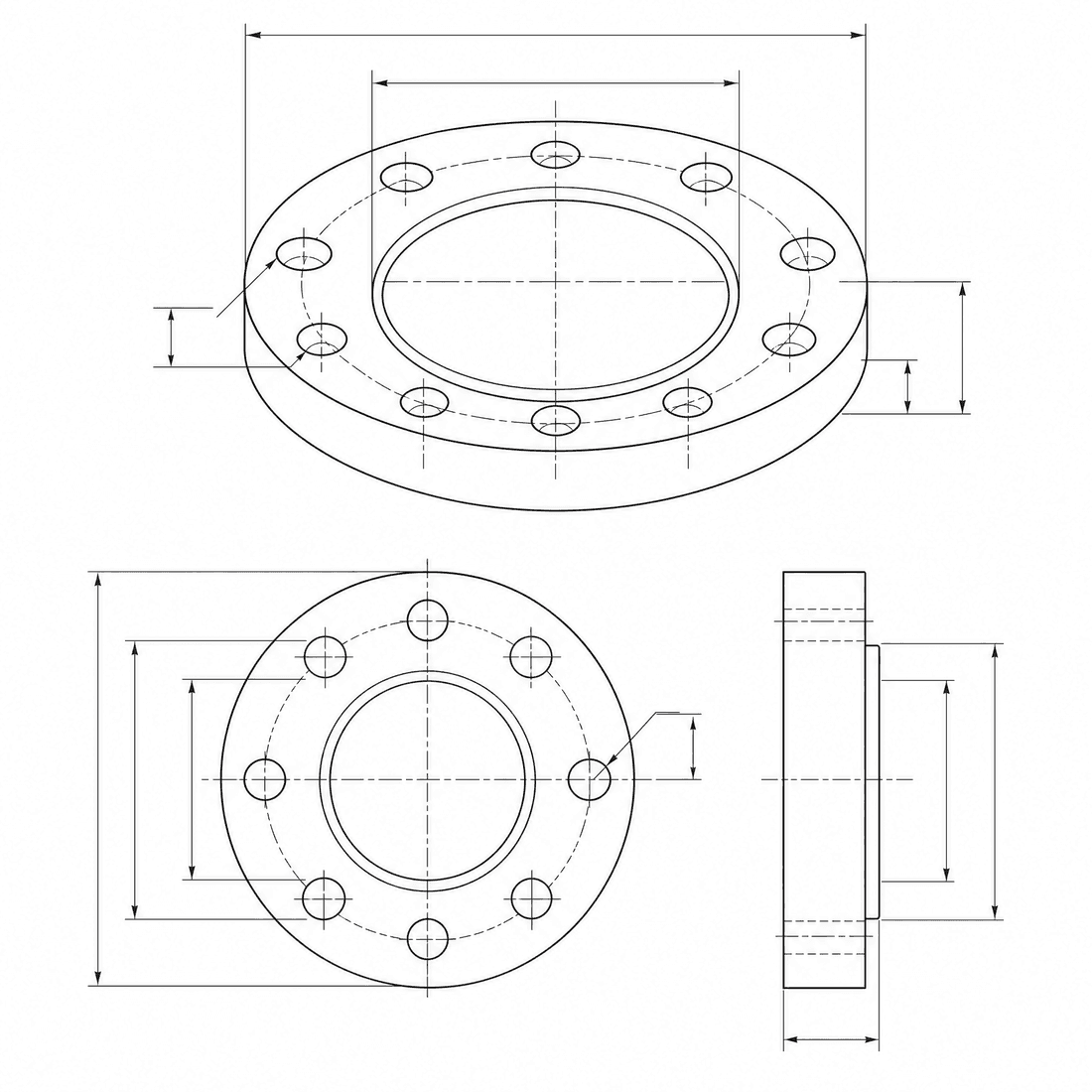
Turn this flange sketch into an engineering drawing with bolt circle, central opening, and dimension lines
Input modes20-tooth spur gear with center bore, keyway, dimension lines, and clean isometric CAD linework
Input modesPipe flange with 6 bolts, central bore, bolt circle, section detail, and technical drawing callouts
 Input modes
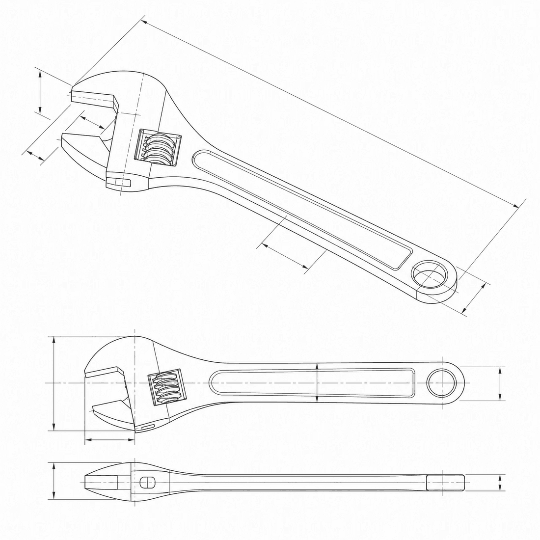
Adjustable wrench with jaw mechanism, thumbwheel, handle grip pattern, and dimension lines
 Input modes
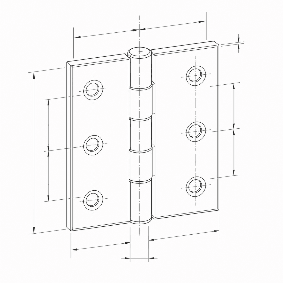
Butt hinge with two leaves, knuckle pin, countersunk screw holes, and dimension annotations
 Input modes
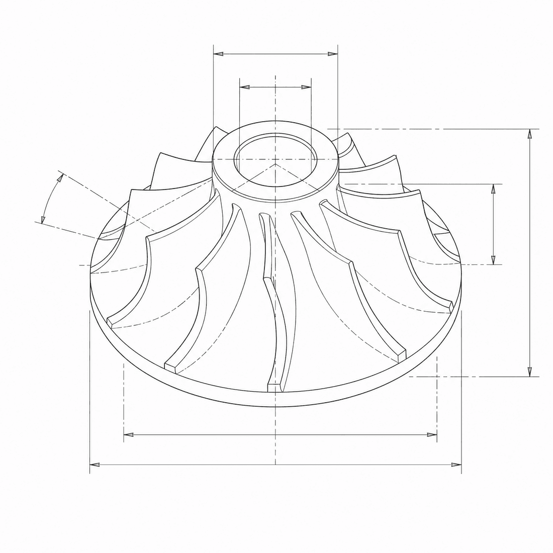
Radial turbine rotor with curved blades, central hub, shaft bore, and technical drawing callouts
Input modesHinged phone stand with folded and open positions, pivot pin, base plate, and dimension lines
 Input modes
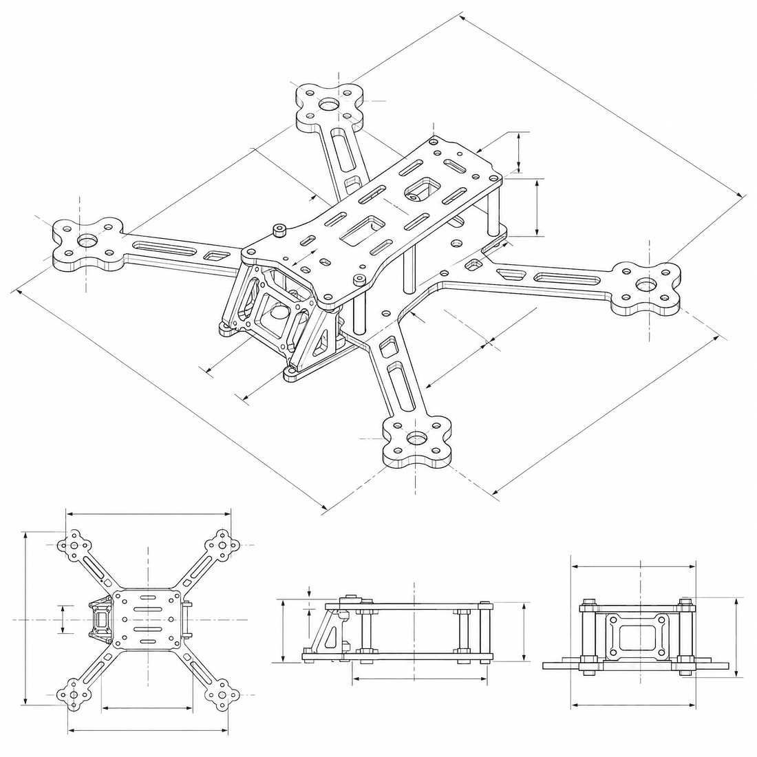
Quadcopter drone frame plate with four motor mounts, center electronics bay, and mounting holes
 Input modes
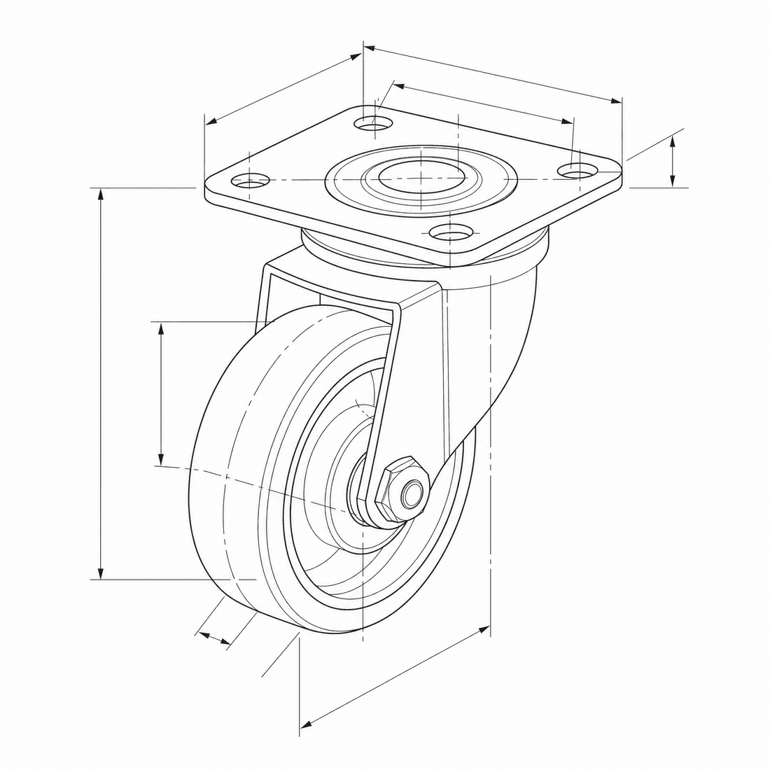
Swivel caster wheel assembly with mounting plate, fork bracket, wheel, and dimension lines
Input modesL-shaped aluminum bracket with four mounting holes, rounded fillets, and dimension annotations
 Input modes
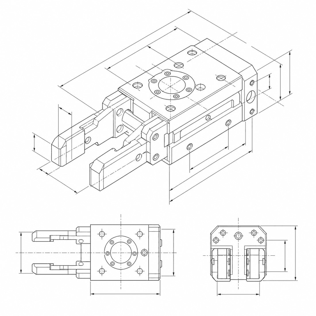
Two-finger robotic gripper jaw with parallel fingers, actuation slots, mounting holes, and CAD annotations
Input modesSmall electronics enclosure with rounded corners, lid seam, screw bosses, vent slots, and CAD annotations
 Input modes
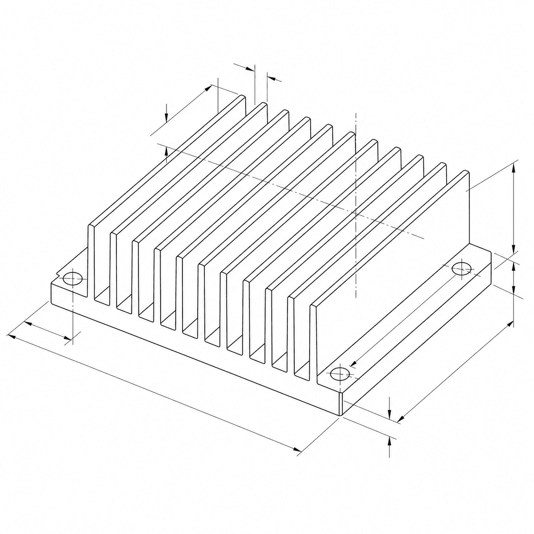
Extruded aluminum heatsink with parallel cooling fins, mounting base, screw holes, and dimension callouts
Drawing stylesPipe flange with a 6-bolt circle and central bore, fully dimensioned with bolt-spacing callouts and a section view
Drawing stylesButt hinge detailed with leaf-length and knuckle-diameter dimensions plus countersunk hole callouts and leader lines
Drawing stylesAdjustable wrench dimensioned across the jaw opening, handle length, and thumbwheel, with annotated leader lines
Drawing stylesRadial turbine rotor with blade-angle callouts, hub-diameter dimensions, and a labeled shaft bore
Drawing stylesSwivel caster assembly with a dimensioned mounting-plate hole pattern, wheel diameter, and overall height
Drawing stylesBlueprint of a quadcopter frame plate on a deep blue engineering board with white linework, motor mounts, and a title block
Drawing stylesBlueprint-style two-finger robotic gripper with white technical linework, actuation slots, and a dimension grid on blue paper
Drawing stylesClassic blueprint of a finned aluminum heatsink on blue paper, showing fin pitch and the mounting-hole layout in white lines
Drawing stylesEngineering blueprint of a spur gear on a blue background with a white tooth profile, pitch circle, and bolt-hole detail
Drawing stylesBlueprint of a radial turbine rotor on a deep blue board with white blade outlines and centerline annotations
Drawing stylesIsometric CAD line drawing of a compact gearbox housing with a removable top cover, four mounting feet, bearing bores, and restrained dimension callouts
Drawing stylesClean 30-degree isometric CAD drawing of an L-shaped motor bracket with slotted mounting holes, gussets, rounded fillets, and visible edge detail
Drawing stylesIsometric technical illustration of a parallel robotic gripper assembly with two jaws, linkage pins, actuator mount, and an exploded spacing between major parts
Drawing stylesIsometric CAD linework of a lightweight quadcopter frame with four motor arms, central electronics plate, standoffs, and symmetrical mounting holes
Drawing stylesExploded isometric CAD drawing of a swivel caster with mounting plate, bearing race, fork, axle, wheel, and fasteners separated along their assembly directions
Drawing stylesClean isometric CAD illustration of an extruded aluminum heatsink with evenly spaced fins, base mounting holes, chamfered corners, and restrained overall dimensions
Drawing styles3D wireframe CAD model of a radial turbine rotor with curved blades, central hub, shaft bore, and thin cyan polygon edges on a dark charcoal background
Drawing stylesTransparent wireframe CAD visualization of an electronics enclosure with internal PCB standoffs, side vents, screw bosses, and a removable lid
Drawing stylesDetailed 3D wireframe model of a swivel caster assembly showing the mounting plate, bearing race, fork, axle, wheel, and internal connections
Drawing stylesWireframe CAD render of an extruded heatsink with evenly spaced fins, base plate, mounting holes, and transparent edge structure
Drawing stylesCyan wireframe CAD model of a two-finger robotic gripper revealing the internal linkage, pivot pins, actuator rod, guide slots, and mounting interfaces
Drawing stylesTransparent 3D wireframe visualization of a quadcopter frame with motor arms, stacked center plates, standoffs, camera mount, and internal cable routes
IndustriesTechnical CAD concept for a 3D-printable camera mounting bracket with a 40 mm base, two M4 clearance holes, triangular gussets, 3 mm walls, and rounded internal corners
IndustriesOrthographic CAD drawing of a snap-fit cable routing clip for a 6 mm cable, with a flexible opening, flat print base, 2.5 mm wall thickness, and dimension callouts
IndustriesDimensioned CAD concept for a small 3D-printed sensor enclosure with a slide-on lid, internal PCB rails, cable opening, four heat vents, and no unsupported overhangs
IndustriesTechnical drawing concept for a single-piece 3D-printed phone stand with a 65-degree viewing angle, charging cable slot, broad stable base, and 4 mm minimum wall thickness
IndustriesOrthographic CAD concept of a 32-tooth prototype spur gear with a 6 mm D-shaped bore, 4 mm face width, hub, tooth profile, and key dimensions for print planning
IndustriesDimensioned CAD concept for a 3D-printed drill guide fixture with two hardened-bushing positions, a flat clamping face, 5 mm walls, alignment stops, and rounded stress-relief corners
IndustriesSolid-shaded CAD viewport concept of a compact handheld barcode scanner with an ergonomic grip, angled scan head, trigger, battery door, and clean enclosure seams
IndustriesIndustrial design CAD concept for a weighted desktop charging dock with a tilted phone cradle, cable channel, soft corner radii, and a two-part enclosure
IndustriesShaded CAD viewport model of a palm-sized wireless controller with two thumb controls, four buttons, a USB-C port, split housing, and ergonomic side grips
IndustriesProduct design CAD render of a compact bladeless desk fan with an oval air loop, adjustable neck, circular base, rear intake vents, and restrained matte surfaces
IndustriesShaded product CAD concept of a compact action camera with a protective lens bezel, side record button, battery hatch, mounting interface, and weather-sealed housing split
IndustriesIndustrial design CAD render of a modular desk task light with a slim LED head, two pivot joints, concealed cable path, weighted base, and replaceable control module
IndustriesOrthographic mechanical engineering drawing of a bearing flange with front, top, and section views, 72 mm bolt circle, four M8 holes, 35 mm bore, centerlines, and dimensions
IndustriesDimensioned engineering drawing of a split shaft coupling with two hubs, keyways, clamping bolts, aligned orthographic views, and a sectional detail through the bore
IndustriesTechnical drawing of a forged lever arm with a pivot bore, slotted linkage end, ribbed center section, overall length dimension, hole callouts, and side profile
IndustriesMechanical assembly drawing of a heavy-duty hinge with two leaves, pin, bushings, countersunk holes, section view, item separation, and critical interface dimensions
IndustriesOrthographic mechanical drawing of a pillow block bearing housing with base mounting slots, split cap, bearing seat section, center height, fillet radii, and bolt callouts
IndustriesMechanical assembly drawing of a compact worm gear reducer with housing, input shaft, worm wheel, output hub, bearing locations, sectional view, and critical shaft-center dimensions
IndustriesEducational CAD diagram of a simple stepped block with aligned front, top, and right-side orthographic views, projection guides, centerlines, and a clean white background
IndustriesClassroom technical diagram of a spur gear showing the tooth profile, pitch circle, root circle, center bore, and clear leader positions without readable labels
IndustriesTeaching example of a pipe flange with an exterior front view beside a hatched section view through the central bore and bolt holes, using clean engineering linework
IndustriesEducational exploded technical drawing of a butt hinge with two leaves, center pin, knuckles, and fasteners separated along the assembly axis in a clear sequence
IndustriesClassroom CAD worksheet diagram of an L-shaped mounting bracket with extension lines, diameter symbols represented as blank callout positions, baseline dimensions, and simple orthographic views
IndustriesEducational technical illustration of a two-link robotic gripper mechanism in open and closed positions with pivot centers, motion arcs, linkage geometry, and a clean comparison layout
ModelsA compact L-shaped mounting bracket with four countersunk holes, 3 mm wall thickness, and rounded outside corners, clean isometric CAD drawing
ModelsA 20-tooth spur gear with a keyed center bore and raised hub, simple technical linework on a white background
ModelsA foldable desktop phone stand with a single hinge, cable opening, and broad base, clean product CAD illustration
ModelsA small rectangular electronics enclosure with a removable lid, four screw bosses, and side ventilation slots, isometric CAD view
ModelsRefine the flange concept into a precise engineering drawing with a six-hole bolt circle, center bore, dimension lines, and section detail
ModelsTurn this rough drone frame plate sketch into a clean high-resolution CAD drawing with symmetric motor mounts and weight-reduction cutouts
ModelsCreate a detailed isometric CAD render of an aluminum heatsink with evenly spaced fins, mounting holes, and a machined base plate
ModelsA two-finger robotic gripper assembly with linkage pivots, actuator mount, fasteners, and an exploded technical presentation
ModelsCreate an exploded CAD-style assembly drawing of a swivel caster showing the mounting plate, bearing race, fork, axle, wheel, fasteners, and aligned assembly guides
ModelsA presentation-ready engineering drawing of a radial turbine rotor with repeated blades, hub and shaft bore, blade-angle callouts, and balanced dimensions
ModelsConvert the reference into a precise butt hinge drawing with countersunk holes, interleaved knuckles, hinge pin, orthographic views, and concise dimensional callouts
ModelsGenerate a detailed adjustable wrench design sheet with an isometric hero view, jaw mechanism detail, thumbwheel, material shading, and key dimensions
ModelsRestyle the drone frame as a crisp engineering blueprint with white linework, symmetric motor mounts, dimension grid, and a restrained title block
ModelsA clean wireframe visualization of a spur gear with visible tooth geometry, pitch circle, keyed bore, and subtle construction lines
ModelsTransform the enclosure reference into a polished industrial-design CAD render while preserving the lid split, vent pattern, ports, and overall proportions
ModelsCreate three visually consistent CAD presentation views of a finned heatsink: technical linework, blue engineering print, and softly shaded aluminum
ModelsA machined valve body with sharp chamfers, resolved fillet radii, counterbored mounting holes, and a threaded side port, clean isometric CAD drawing with two enlarged edge details
ModelsAn L-shaped mounting bracket drawn with deliberately crisp edge definition: 1 mm chamfers on every outside edge, 3 mm fillets at the web, and countersunk holes shown in section
 Models
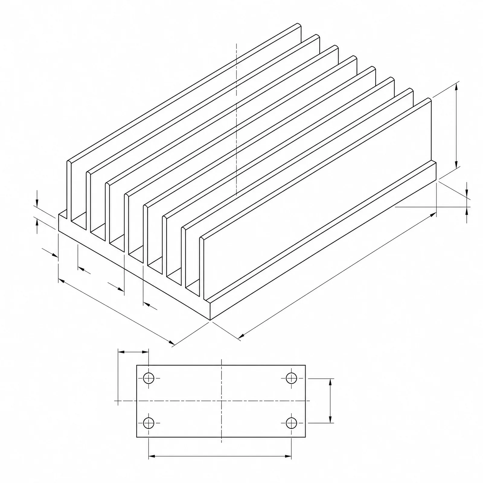
An extruded aluminium heatsink shown as a clean CAD line drawing with straight parallel fins, a flat machined base, and a sectioned end view showing fin pitch and base thickness
 Models
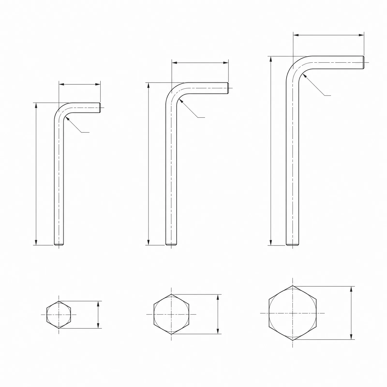
A set of three L-shaped hex keys laid out in a row with across-flats dimensions, bend radii, and a consistent line weight throughout
 Models
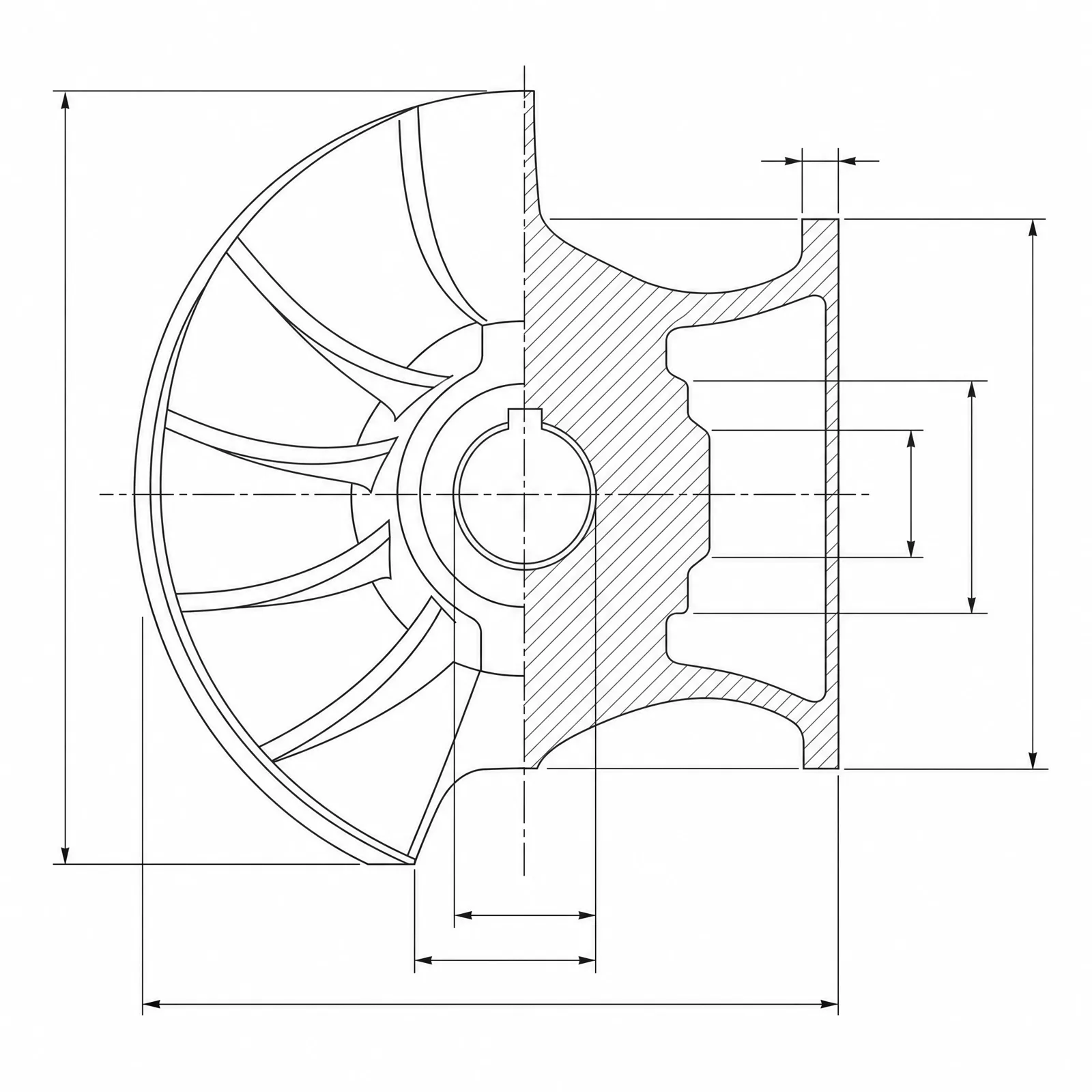
A centrifugal impeller shown as a half section through the hub with hatched cut faces, blade roots, shroud thickness, and a keyed shaft bore, densely dimensioned
ModelsA two-finger robotic gripper assembly drawing with linkage pivots, actuator mount, fastener callouts, and an exploded arrangement showing every component separately
 Models
A concealed cabinet hinge with a cup boss, mounting plate, and adjustment screws, drawn as front and side orthographic views with full dimensioning
 Models
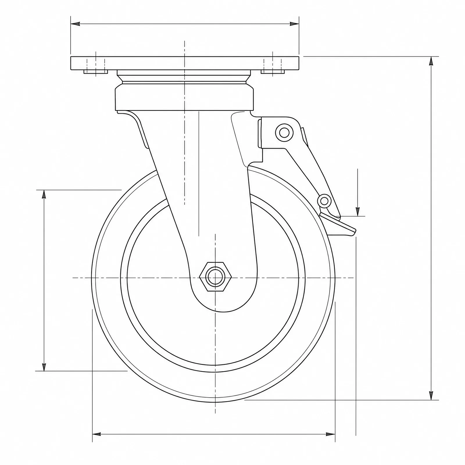
A braked swivel caster drawn in side view with the brake lever engaged against the wheel tread, showing the fork, axle, bearing race, and mounting plate together
ModelsA planetary gearbox shown as a large isometric cutaway with the sun gear, planet gears, ring gear, and carrier all resolved in fine detail, suitable for a large print
 Models
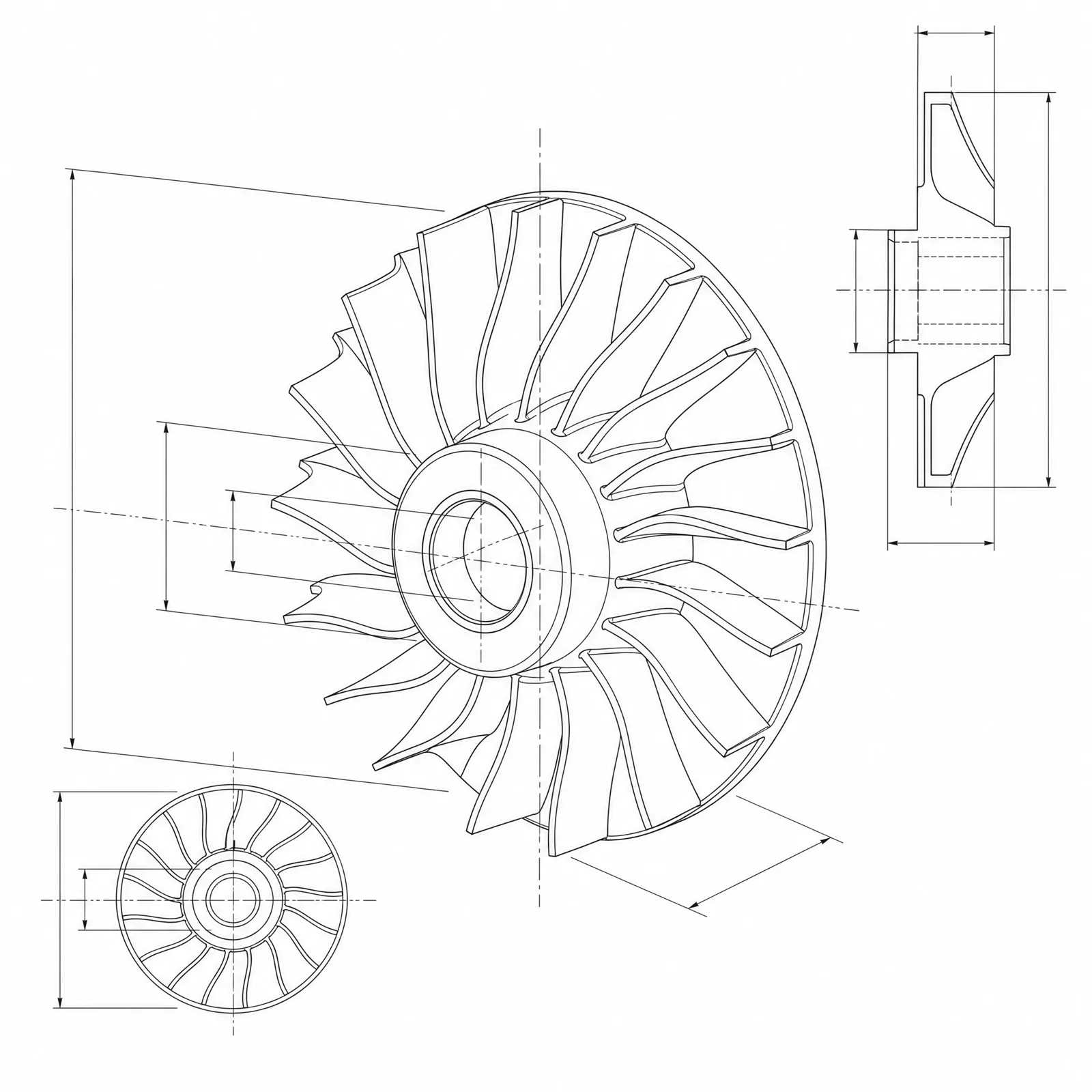
A radial turbine rotor with curved blades, a central hub, and a shaft bore, drawn at high resolution so every blade edge stays crisp when printed large
ModelsA quadcopter frame plate with symmetric motor mounts, weight-reduction cutouts, and electronics mounting holes, drawn as a detailed flat pattern with dimensions
 Models
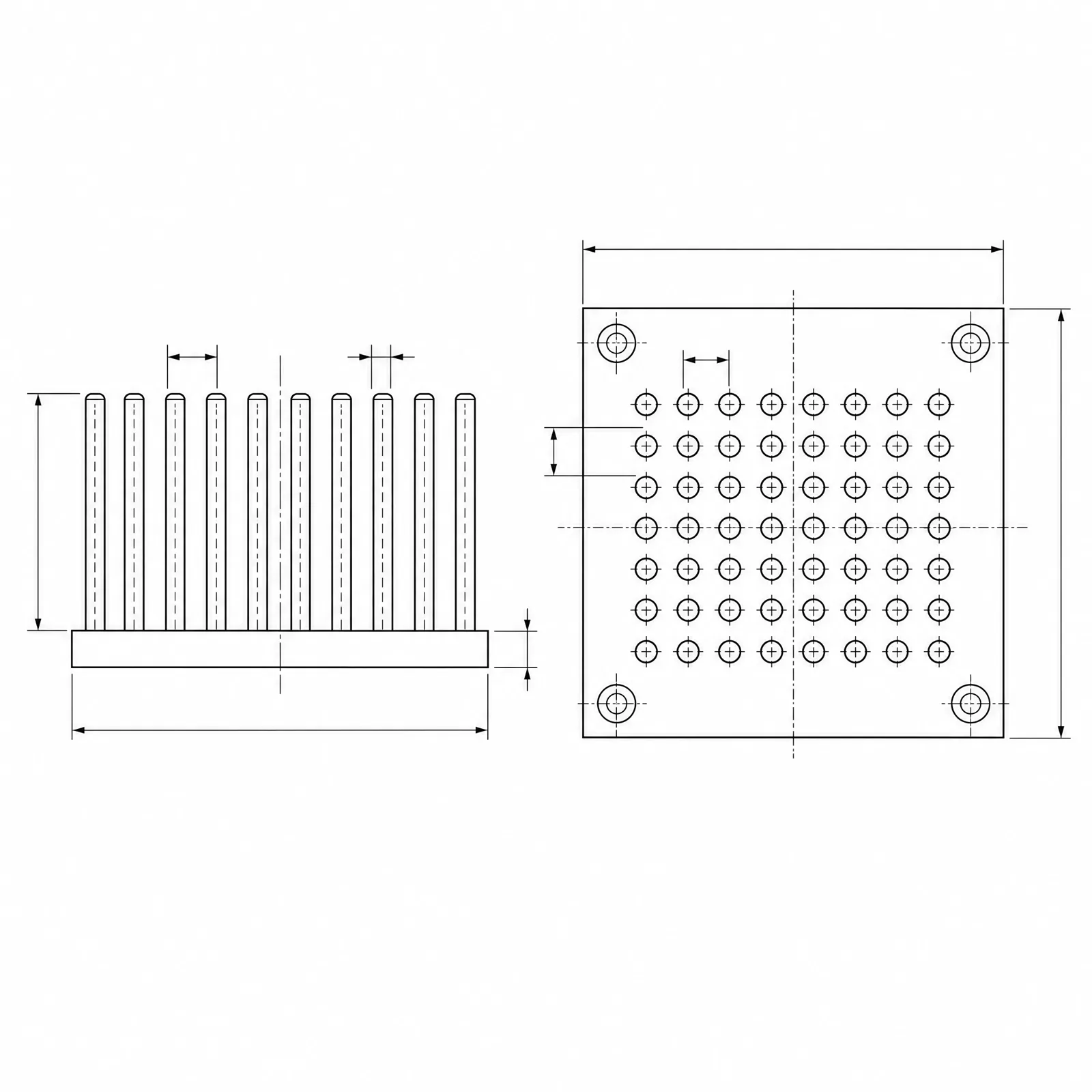
A pin-fin heatsink with a square array of cylindrical pins on a base plate, shown as front and top orthographic views with pin pitch and corner hole spacing
Part templatesL-shaped aluminum mounting bracket, 80 mm tall by 50 mm deep, 5 mm plate thickness, four M6 mounting holes, 8 mm inside fillet, clean isometric CAD-style technical drawing with dimension lines
Part templatesU-shaped motor support bracket made from bent steel plate, slotted base holes, circular motor pilot opening, side stiffening ribs, front and isometric CAD-style views with key dimensions
Part templatesTriangular shelf corner bracket with two perpendicular mounting faces, six countersunk screw holes, central weight-reduction cutout, rounded outer corners, precise CAD-style line image
Part templatesCompact sensor adjustment bracket with a curved angle slot, pivot hole, two base slots, folded sheet-metal construction, exploded CAD-style image showing fastener positions
Part templates24-tooth spur gear with involute tooth profile, 60 mm pitch diameter, 12 mm center bore, 4 mm keyway and raised hub, isometric CAD-style technical image with pitch circle and dimensions
Part templatesTiming pulley with 30 rounded belt teeth, twin flanges, six circular weight-reduction holes, clamping hub and shaft bore, clean front and section CAD-style drawing
Part templatesMatched 90-degree bevel gear pair, one 16-tooth pinion and one 32-tooth gear, tapered teeth, keyed shafts, exploded isometric CAD-style assembly image
Part templatesBronze worm wheel concept with 40 helical teeth, bolted center hub, six-spoke web and shaft bore, sectioned CAD-style image showing hub and rim proportions
Part templatesRaised-face pipe flange with 120 mm outside diameter, 55 mm bore, six equally spaced M10 bolt holes on a 90 mm bolt circle, section and front CAD-style views with dimensions
Part templatesSquare motor mounting flange, 100 mm by 100 mm, central bearing pilot, four corner slots, stepped recess and rear stiffening ribs, isometric CAD-style technical image
Part templatesWeld-neck flange with tapered hub, raised sealing face, eight-hole bolt circle and pipe bore, half-section CAD-style image emphasizing neck transition and flange thickness
Part templatesTwo-piece split clamp flange for a tube, semicircular bore, paired clamping bolts, locating shoulder and counterbores, exploded CAD-style image with assembly alignment
Part templatesSymmetrical X-frame quadcopter top plate, 250 mm motor-to-motor span, four slotted motor mounts, central flight-controller pattern and cable cutouts, top and isometric CAD-style views
Part templatesFive-inch racing drone sandwich frame with separate carbon-fiber arms, top and bottom plates, standoff holes, camera cage and battery strap slots, exploded CAD-style assembly image
Part templatesCompact foldable quadcopter frame with four hinged arms, locking pivots, central electronics shell, landing feet and motor wire channels, open and folded CAD-style concept views
Part templatesHexacopter center frame with six radial tube clamps, twin circular equipment plates, vibration-isolated payload mount and landing-gear sockets, dimensioned isometric CAD-style image
Part templatesFoldable desktop phone stand with a 70 mm cradle, adjustable friction hinge, charging-cable slot, rubber feet and folded position, open and closed CAD-style product views
Part templatesWeighted aluminum phone charging stand, angled backrest, recessed wireless charging puck, cable channel through the stem and non-slip base pad, sectioned CAD-style image
Part templatesDesk-edge clamp phone holder with screw clamp, two-link articulated arm, ball joint and spring-loaded phone jaws, exploded CAD-style assembly image
Part templatesTwo-piece flat-pack plywood phone stand using interlocking slots, 15-degree viewing angle, front lip and charging cable opening, assembled and separated CAD-style views
Part templatesTwo-piece ABS electronics enclosure, 120 by 80 by 35 mm, four internal screw bosses, recessed lid, side ventilation slots, USB-C cutout and exploded CAD-style image
Part templatesErgonomic handheld enclosure with split housing, four snap hooks, internal PCB rails, battery door, button openings and rounded grip surfaces, sectioned CAD-style product image
Part templatesWeather-resistant outdoor sensor enclosure with perimeter gasket groove, captive lid screws, cable gland bosses, wall-mount tabs and drip edge, exploded CAD-style technical image
Part templatesCompact DIN-rail electronics enclosure with removable terminal covers, vent slots, PCB card guides, label recess and rear rail clip, front and isometric CAD-style views
Part templatesBench drill guide fixture with base plate, two locating pins, replaceable hardened drill bushing, toggle clamp and adjustable end stop, exploded CAD-style assembly image
Part templatesPair of CNC vise soft jaws with mirrored part pockets, datum step, relief grooves and mounting counterbores, top and isometric CAD-style images showing the clamped workpiece
Part templatesPCB assembly fixture with ESD-safe base, spring locating pins, hinged top plate, connector access windows and four quick-release latches, open CAD-style technical image
Part templatesModular tube welding fixture on a slotted base plate, two V-block supports, adjustable end locator and horizontal toggle clamps, dimensioned isometric CAD-style image
Part templatesExtruded aluminum heatsink, 120 mm by 80 mm base with a 6 mm base plate, 21 straight fins 30 mm tall and 1.5 mm thick on a 5.5 mm pitch, four M4 corner mounting holes, isometric CAD-style technical drawing with fin-pitch and base dimensions
Part templatesPin-fin heatsink with a 60 mm square base, an 11 by 11 grid of 3 mm round pins 25 mm tall, chamfered base edges and two diagonal M3 mounting holes, top and isometric CAD-style views with pin-pitch callouts
 Part templates
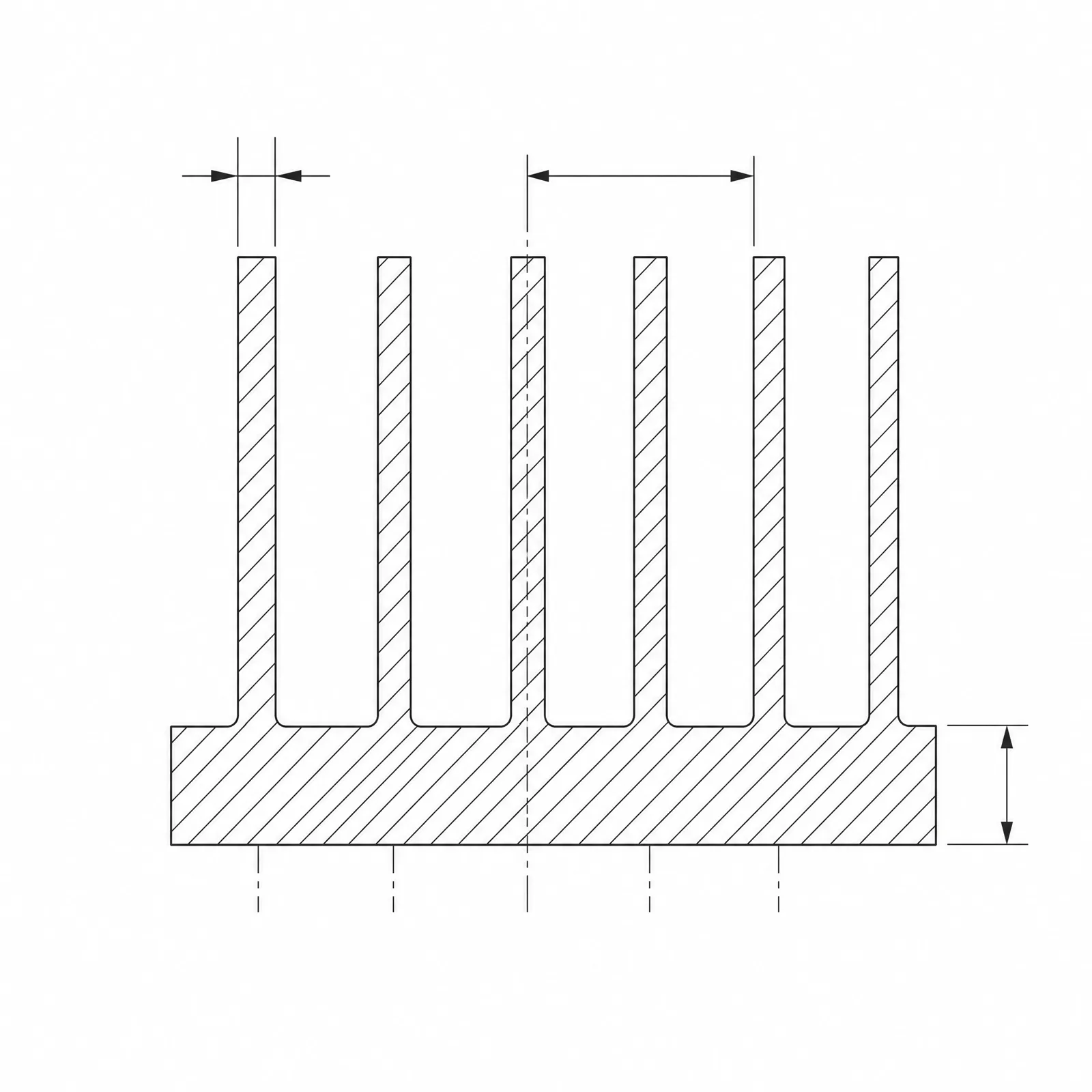
Section view of a bonded-fin heatsink showing 8 mm base thickness, 2 mm fin roots with 1 mm root fillets, a 40 mm component contact pad and an embedded 8 mm heat pipe, CAD-style drawing with section hatching and leader dimensions
Part templatesFinned aluminum heatsink as a clean CAD-style line drawing with parallel cooling fins, mounting base, corner screw holes and airflow direction arrows along the fin channels
 Part templates
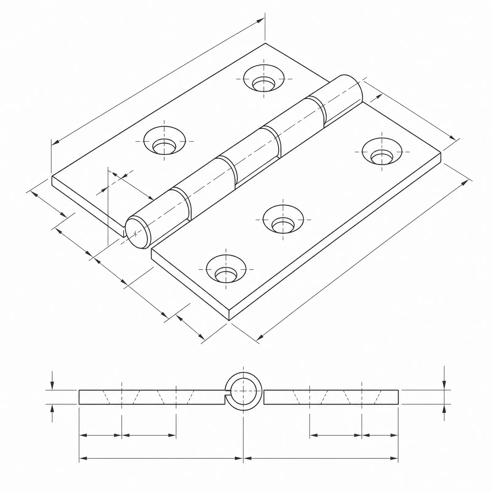
Steel butt hinge with two 75 mm by 30 mm leaves, 2.5 mm plate thickness, five knuckles on a 6 mm pin, four countersunk 4.5 mm screw holes per leaf, flat CAD-style technical drawing with leaf, knuckle and hole-spacing dimensions
 Part templates
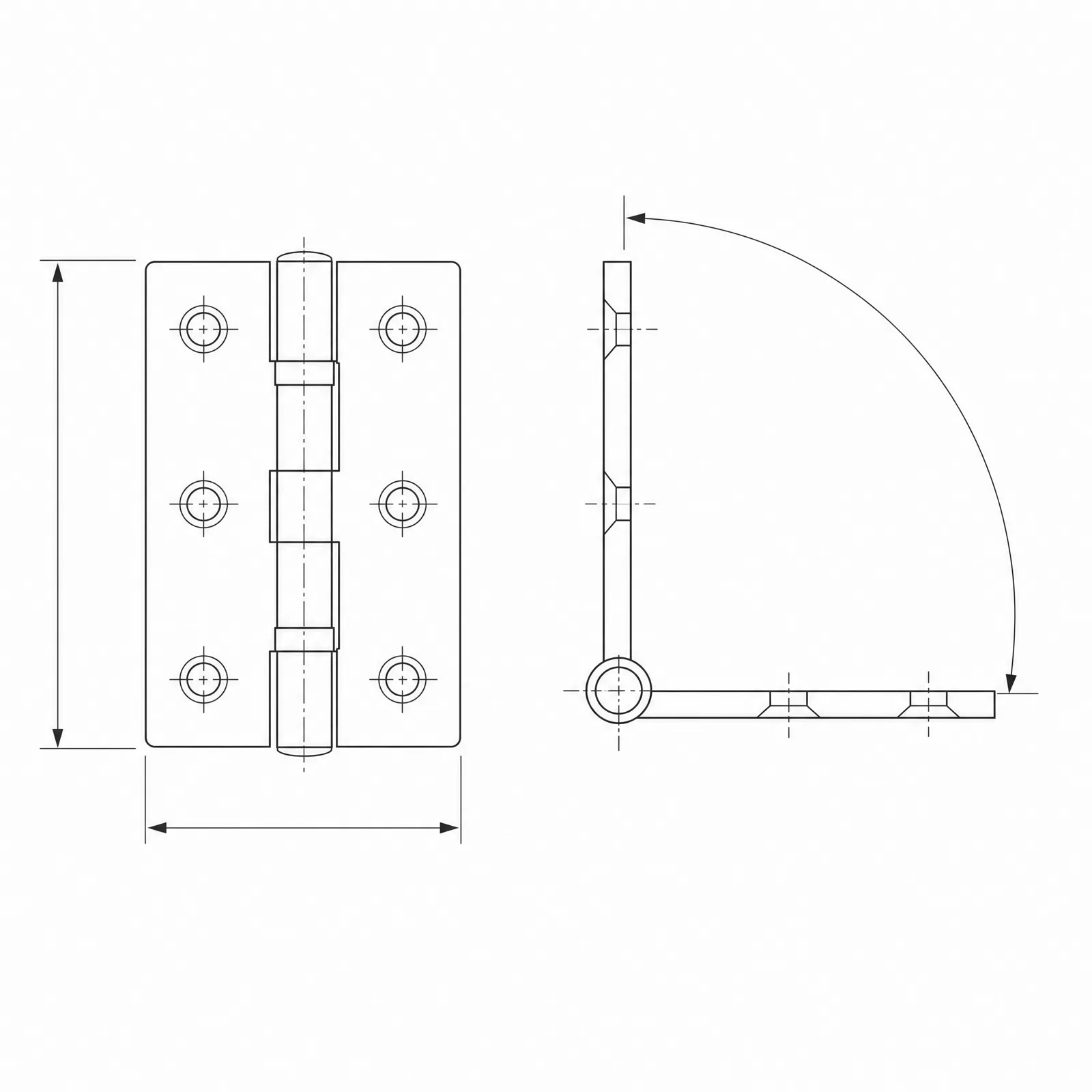
One hinge drawn twice, closed flat at 0 degrees and opened to 110 degrees, with the pin axis marked, the swing arc annotated, and leaf overlap and knuckle interleaving visible, CAD-style technical drawing
Part templatesConcealed European cabinet hinge with a 35 mm cup bored to 12.5 mm depth, cross mounting plate, four-bar linkage arm and two adjustment screws, section and isometric CAD-style views with the cup-to-edge distance called out
Part templatesButt hinge as a clean CAD-style line drawing with two interleaved leaves, a full-length knuckle pin, countersunk screw holes and dimension callouts on the leaf outline
 Part templates
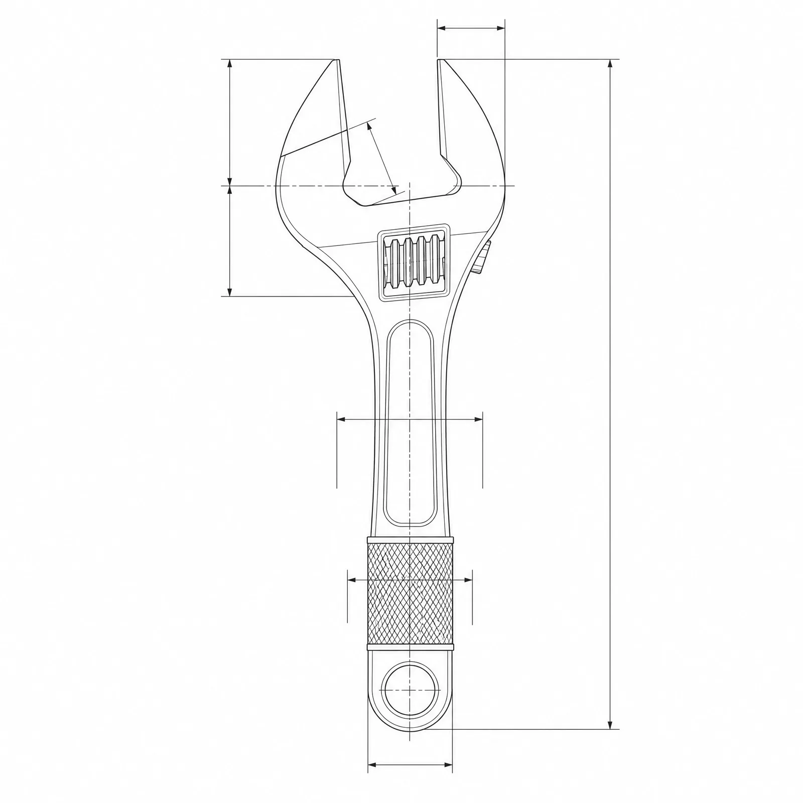
250 mm adjustable wrench with a 30 mm maximum jaw capacity, worm-screw thumbwheel, sliding jaw rack, 15-degree head offset and a knurled handle, flat CAD-style technical drawing with jaw-capacity and overall-length dimensions
 Part templates
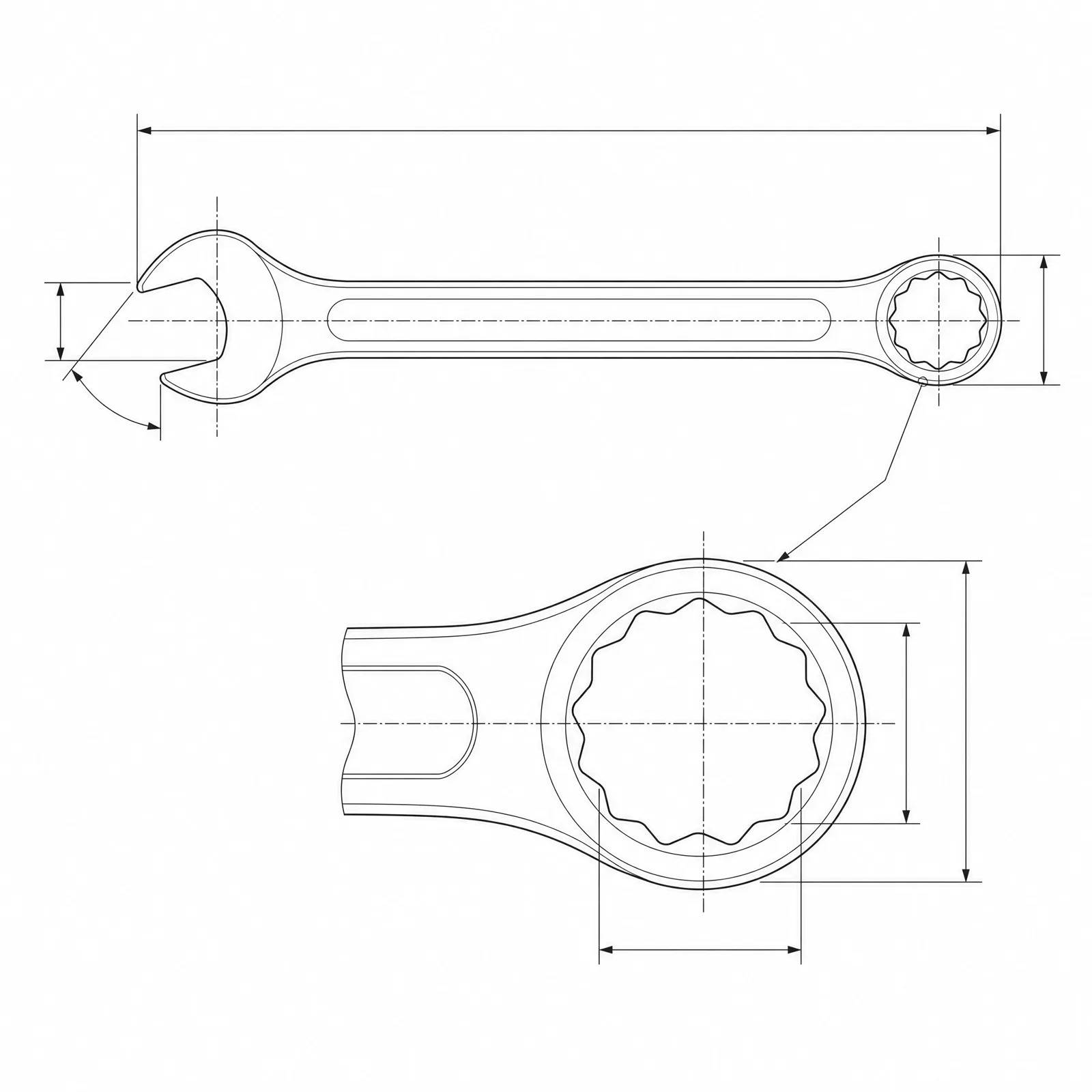
13 mm combination wrench with a 15-degree offset open end and a 12-point box end cranked 15 degrees, 175 mm overall length and an I-beam shank profile, CAD-style plan view plus an enlarged box-end detail
Part templatesLong-arm ball-end hex key set in 2, 2.5, 3, 4, 5 and 6 mm across-flats sizes, chamfered ends, 90-degree bend with short and long arms dimensioned, CAD-style technical drawing arranged in size order
Part templatesAdjustable wrench as a clean CAD-style line image showing the jaw mechanism, thumbwheel, handle profile and overall dimension lines
 Part templates
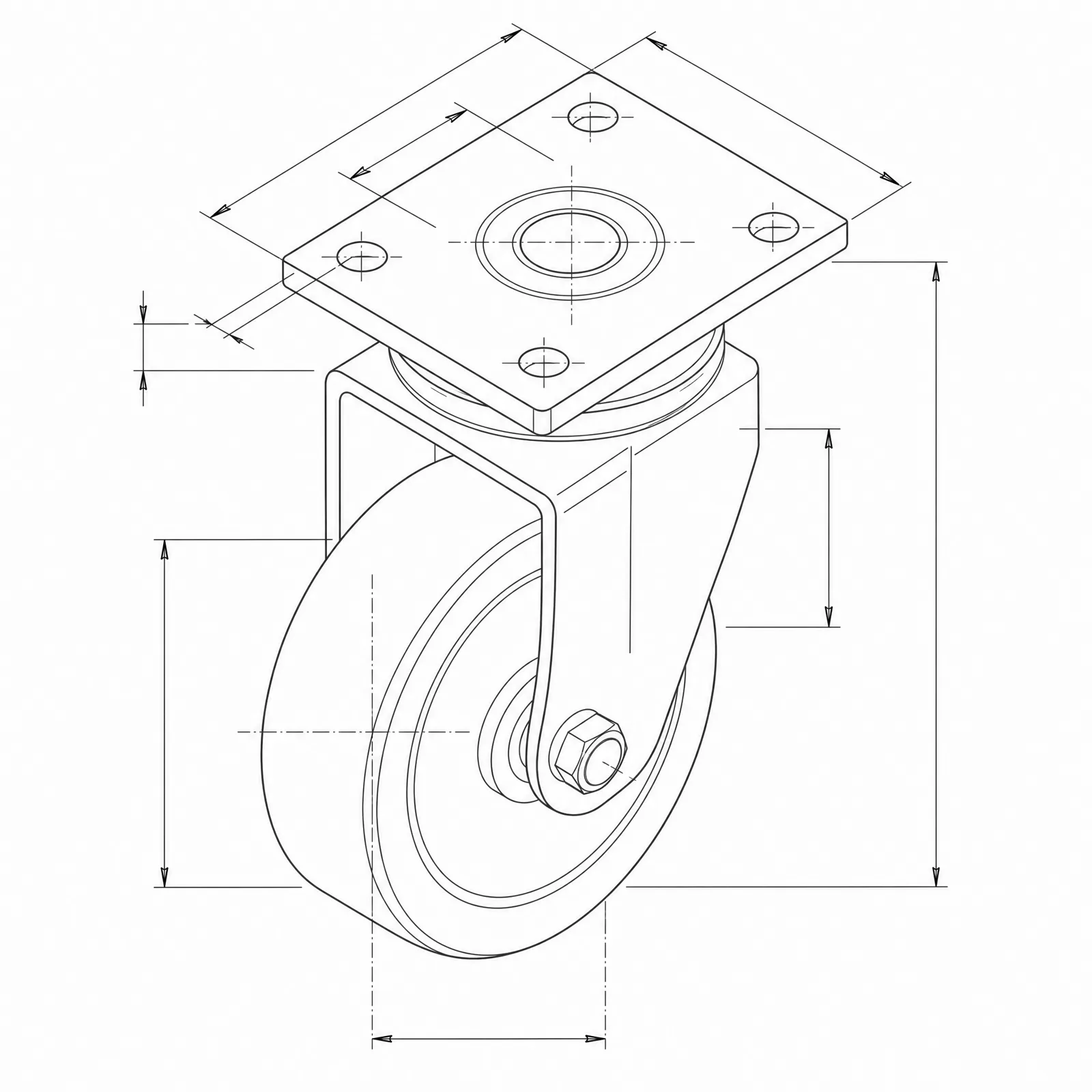
Swivel caster with a 100 mm polyurethane wheel, 32 mm tread width, pressed steel fork, double-ball kingpin race, 40 mm swivel offset and 128 mm overall mounted height, side and isometric CAD-style views with dimensions
 Part templates
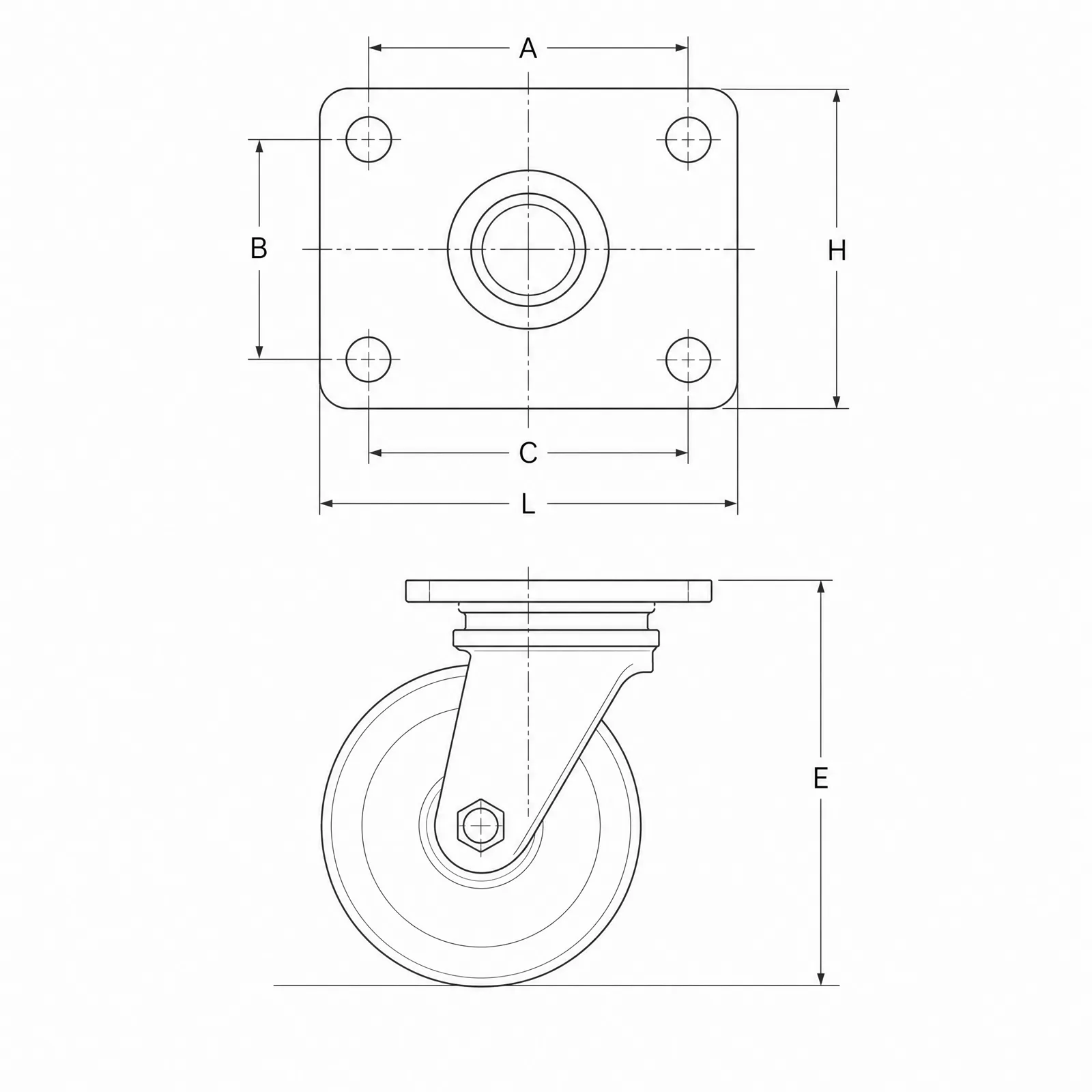
Top view of a caster mounting plate, 105 mm by 85 mm with rounded corners, four 9 mm bolt holes on an 80 by 60 mm pattern, plate-thickness callout and the swivel sweep circle drawn in phantom line, CAD-style technical drawing
Part templatesSwivel caster with a total-lock brake pedal that stops both the tread and the swivel, 125 mm wheel, threaded-stem mounting, brake shown engaged and released, exploded CAD-style drawing with axle, bearing and pedal linkage labeled
Part templatesSwivel caster wheel assembly as a clean CAD-style line image with the mounting plate, fork bracket, wheel and overall height dimension lines
Part templatesRadial inflow turbine rotor with 13 blades, 120 mm outer diameter, 45 mm hub diameter, a 20 mm shaft bore with a 6 mm keyway and a scalloped back face, isometric CAD-style technical drawing with blade and hub dimensions
 Part templates
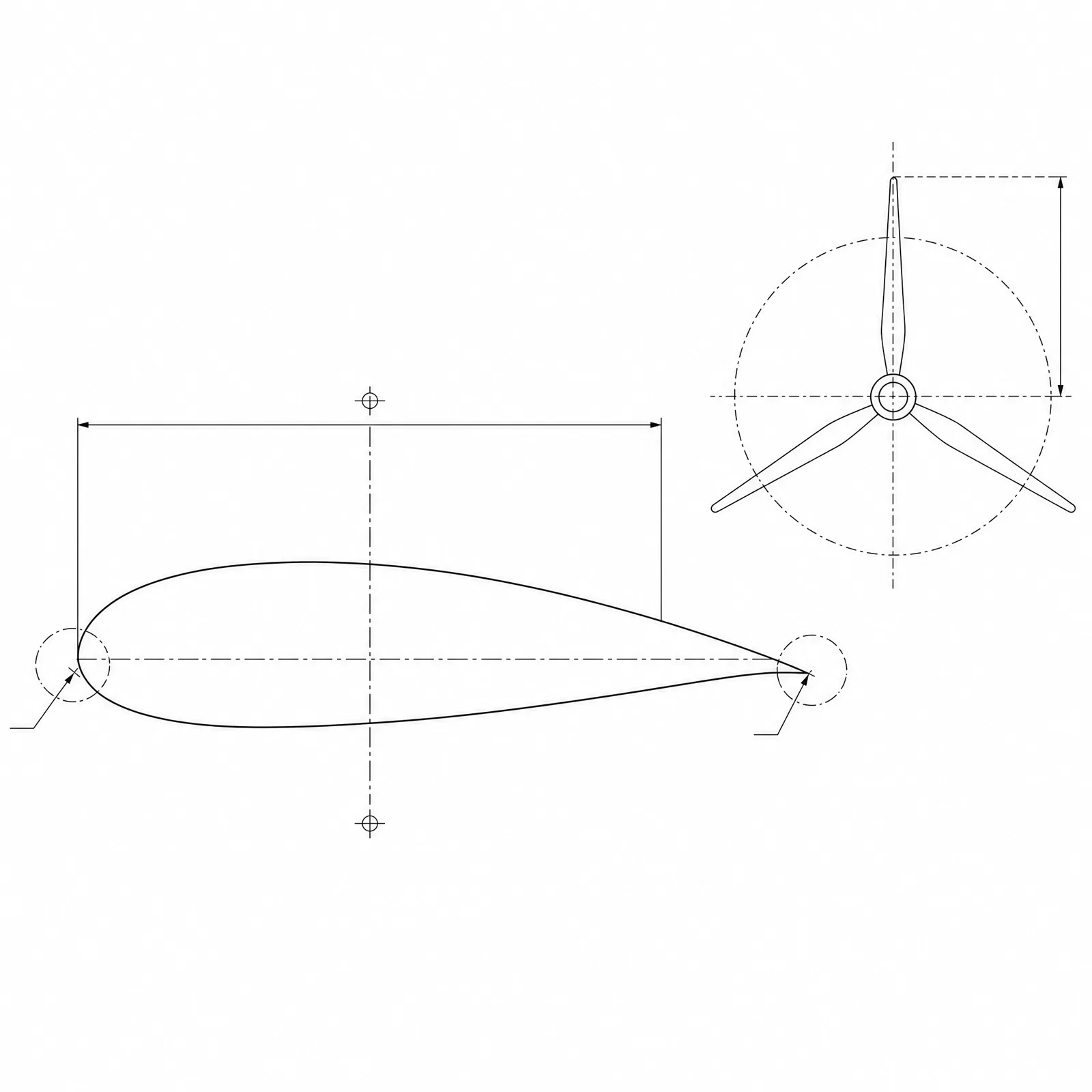
Single turbine blade profile as a CAD-style study showing leading and trailing edge radii, the camber line, chord length, a 32-degree inlet angle, an 18-degree outlet angle and the root fillet, drawn over an annotated coordinate grid
Part templatesSection view of a shrouded centrifugal impeller with 9 backward-curved blades, 180 mm outer diameter, 60 mm eye diameter, 25 mm bore, shroud and hub wall-thickness callouts and hatched cut faces, CAD-style technical drawing
Part templatesRadial turbine rotor as a clean CAD-style line image with curved blades, a central hub, shaft bore and dimension callouts on the blade tips
Input modesCreate a dimensioned CAD-style drawing of an L-shaped 6061 aluminum bracket, 80 x 50 x 5 mm, with four M6 mounting holes, 8 mm corner fillets, one 30 mm adjustment slot, aligned orthographic views, and an isometric reference view.
Input modesCreate a CAD-style product drawing of a 120 x 75 x 32 mm two-piece electronics enclosure with 2.5 mm walls, four PCB bosses, USB-C opening, side vents, recessed lid, exploded view, and neutral shaded surfaces.
Input modesCreate a technical CAD drawing of a 24-tooth module 2.5 spur gear with 12 mm keyed bore, 20 mm face width, raised hub, pitch circle, axial section, and an isometric overview.
Input modesConvert this rough bracket sketch into a clean dimensioned CAD drawing. Preserve the outer proportions and four mounting holes, resolve the bend and gusset geometry, correct symmetry, and show aligned orthographic views plus one isometric reference.
Input modesConvert this flange sketch into a clean technical drawing. Preserve the central bore and six-hole pattern, regularize the bolt circle, infer a raised face, and show a front view, axial section, centerlines, and restrained diameter callouts.
Input modesConvert this rough quadcopter frame sketch into a clean isometric CAD concept. Preserve the four-arm layout and central electronics bay, correct symmetry, clarify motor mounts and fastening holes, and use neutral shaded surfaces with visible edges.
Input modesCreate a reusable CAD example of a 20-tooth spur gear with keyed bore, raised hub, pitch circle, axial section, and clean dimension callouts on a 4:3 technical drawing sheet.
Input modesCreate a reusable shaded CAD product example of a foldable phone stand with hinge, cable slot, non-slip base, folded and open positions, and a clean wide presentation composition.
Input modesCreate a reusable isometric CAD example of a compact drill fixture with workpiece, datum stops, two toggle clamps, replaceable drill bushings, tool access, and numbered interface callouts.
Drawing stylesCreate a formal technical drawing of a 120 mm OD raised-face flange with 55 mm bore, 16 mm thickness, six 11 mm holes on a 90 mm PCD, front view, axial section, isometric reference, centerlines, diameter callouts, and a compact blank title block. Treat dimensions as conceptual and verify separately.
Drawing stylesCreate a formal exploded technical drawing of a heavy-duty hinge assembly with two leaves, removable pin, two bushings, countersunk mounting holes, assembled view, exploded view, section through the knuckle, numbered balloons, and a compact revision title block.
Drawing stylesCreate a formal technical drawing of a two-piece electronics enclosure, 120 x 80 x 35 mm with 2.5 mm walls, four PCB bosses, USB-C opening, vent slots, front and section views, enlarged boss and snap-fit details, conceptual datum references, and a compact title block.
 Drawing styles
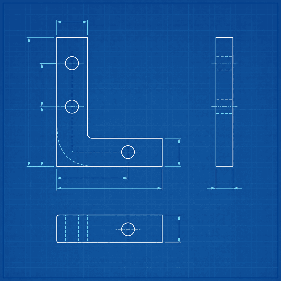
Create a deep-blue engineering blueprint of a quadcopter frame with one large central isometric view, four smaller motor-mount and electronics-bay details, balanced white line hierarchy, key dimensions, numbered callouts, and a thin engineering border.
Drawing stylesCreate a classic blueprint sheet of a two-finger robotic gripper shown as an exploded assembly sequence with base, slides, jaws, links, pins, and fasteners. Use dense white technical linework, numbered balloons, assembly arrows, and a compact blank title block.
Drawing stylesCreate an educational blueprint diagram of a spur gear showing tooth profile, pitch circle, root circle, outside diameter, center bore, and a simple three-stage construction sequence. Use balanced white linework, key numbered callouts, and an engineering border.
Drawing stylesCreate a precise isometric CAD-style technical illustration of a compact gearbox housing with a removable top cover, four mounting feet, bearing bores, ribs, and aligned fasteners. Use standard true-isometric axes at 30 degrees, view from the front-right-top corner, apply technical line weights and subtle neutral face shading, and keep all components assembled.
Drawing stylesCreate a cutaway isometric CAD illustration of a compact motor bracket with a cylindrical locating bore, slotted base holes, triangular gussets, counterbores, and internal clearances. View it from the front-left-top corner, use strong silhouettes with fine internal edges, restrained hidden lines, and light contact depth.
Drawing stylesCreate an exploded isometric CAD line drawing of a swivel caster with mounting plate, bearing race, fork, axle, spacers, wheel, and fasteners. Separate components evenly along their assembly axes, view from the front-right-top corner, use uniform fine linework, and render without perspective convergence.
Drawing stylesCreate a dense 3D wireframe CAD visualization of a radial turbine rotor with curved blades, a central hub, shaft bore, fillets, and rotational symmetry. Use a three-quarter perspective camera, fine cyan edges on charcoal, faint ghosted surfaces, and faded occluded edges.
Drawing stylesCreate an isometric wireframe CAD visualization of a quadcopter frame with four motor arms, stacked center plates, standoffs, camera mount, battery tray, and internal cable routes. Use balanced topology, cyan lines on charcoal, section transparency, and low-opacity hidden edges.
Drawing stylesCreate a wireframe CAD mechanism study of a two-finger robotic gripper showing jaws, pivot pins, actuator rod, guide slots, and mounting interfaces. Use blue lines on white, balanced feature topology, dashed hidden edges, transparent outer links, and aligned orthographic views.
IndustriesCreate a CAD-style concept visual for a 3D-printed PETG camera mounting bracket with a 40 mm base, two M4 clearance holes, triangular gussets, 3 mm nominal walls, 0.3 mm mating clearance, rounded internal corners, and the broad base placed on the print bed. Clearly label it as a concept visual only, not an STL or validated printable model.
IndustriesCreate a CAD-style concept visual for a two-part 3D-printed ASA sensor enclosure with 2.4 mm nominal walls, 0.4 mm lid clearance, four screw bosses, vent slots, a cable-gland opening, filleted corners, and the main shell printed on its side. Present dimensions as planning targets only and state that the image is not an STL or manufacturing-validated model.
IndustriesCreate a dimensioned CAD-style concept visual for a 3D-printed PLA drill guide fixture with two bushing locations, a flat clamping face, 5 mm walls, 0.2 mm bushing clearance, alignment stops, and rounded stress-relief corners. Show it at a 35-degree build angle with conceptual support regions. This is a planning image only, not an STL or verified printable geometry.
IndustriesCreate a shaded product-design CAD concept of a compact handheld barcode scanner with an angled scan head, ergonomic grip, trigger, battery door, protective bumper, and clean enclosure seams. Use rugged dark polymer with textured grip zones and metal hardware, show a three-quarter hero view, and place it in a practical workshop context.
IndustriesCreate a product-design CAD concept of a compact desktop charging dock with a weighted base, angled device cradle, concealed cable exit, status light, anti-slip foot, and precise part breaks. Use bead-blasted aluminum with dark glass and minimal color breaks, show aligned orthographic views, and present it in a clean desk workflow.
IndustriesCreate an exploded product-design CAD concept of a compact smart-appliance controller with front display glass, rotary control, inner chassis, PCB, rear housing, wall mount, and fasteners. Use warm white polymer with soft-touch gray accents, separate materials clearly, and place the exploded assembly on a neutral design-studio background.
IndustriesCreate an ISO metric mechanical detail drawing of a flanged hub with aligned front and side views plus a full center-plane section. Show the stepped shaft bore, keyway, bearing shoulder, six-hole bolt circle, flange thickness, centerlines, datums, and restrained dimension targets using first-angle projection conventions.
IndustriesCreate an ASME-style mechanical assembly drawing of a compact gearbox subassembly using a half section. Show housing halves, two shafts, meshing gears, bearing seats, retaining rings, cover fasteners, item balloons, centerlines, and shaft-bearing interfaces with third-angle projection markers. Dimensions are review targets only.
IndustriesCreate a JIS-style metric interface-control drawing for an extruded aluminum heatsink. Show the mounting envelope, base contact face, four-hole pattern, fin keep-out zone, connector clearance, mounting datums, and a local detail section through a threaded insert. Use restrained engineering annotations and clearly marked reference dimensions.
IndustriesCreate a beginner educational CAD diagram of a simple stepped block. Place a small isometric reference beside aligned front, top, and right-side orthographic views, add projection guides, centerlines, numbered feature matches, and short plain-language labels. The objective is to recognize projection conventions and connect the same feature across views.
IndustriesCreate an intermediate educational CAD diagram explaining a full section through a flanged bearing block. Show the cutting-plane arrows on the exterior view, the resulting hatched section, centerlines, bore and counterbore, and numbered callouts linking each internal feature. The objective is to interpret hidden geometry from a section view.
IndustriesCreate an advanced educational technical diagram of a two-link robotic gripper in open and closed positions. Mark fixed and moving pivots, link lengths, actuator direction, jaw paths, motion arcs, and constrained degrees of freedom using concise standards-based notation. The objective is to explain how the linkage converts actuator travel into jaw motion.
ModelsA compact L-shaped mounting bracket with four countersunk holes, 3 mm wall thickness, and rounded outside corners, one clean isometric technical drawing on a white background
ModelsA compact 20-tooth spur gear with a keyed center bore and raised hub, one centered isometric wireframe CAD view with clean construction lines
ModelsA compact electronics enclosure with a removable lid, four internal screw bosses, side ventilation slots, and two cable ports, one clean three-quarter isometric CAD view
ModelsRefine this flange sketch into a precise engineering drawing. Preserve the center bore, six-hole bolt circle, stepped rim, and symmetry. Add orthographic views, concise dimension lines, and one section detail.
ModelsTurn this rough drone frame sketch into a clean CAD presentation. Preserve four symmetric motor mounts, the central electronics bay, arm widths, and weight-reduction cutouts. Use crisp technical linework and a wide layout.
ModelsCreate a detailed exploded CAD presentation of a two-finger robotic gripper assembly with linkage pivots, actuator mount, jaw plates, bearings, and fasteners. Align components along assembly guides and keep the mechanism hierarchy clear.
ModelsCreate a presentation-ready exploded CAD design sheet of a swivel caster assembly. Show the mounting plate, bearing race, fork, axle, wheel, washers, locknut, and fasteners in correct hierarchy. Use one large exploded isometric view, two detail insets for the bearing stack and axle connection, aligned assembly guides, concise part labels, critical dimensions, and restrained material callouts. Keep spacing clean and mechanically plausible.
ModelsConvert the supplied hinge reference into a precise engineering design sheet. Preserve the leaf proportions, interleaved knuckle count, hinge pin position, and countersunk-hole pattern. Add front, side, open isometric, and pin-detail views. Include concise dimensions and labels without obscuring the geometry. Use crisp technical linework on a clean background.
ModelsGenerate a detailed CAD product study of an adjustable wrench. Define the fixed jaw, sliding jaw, worm gear, rack teeth, axle, handle profile, hanging hole, and transition fillets. Present one large three-quarter hero view, one keyed section through the jaw mechanism, and two close-up callouts for the worm gear engagement and jaw scale. Add only essential dimensions, material notes, and clear labels. Maintain realistic mechanical relationships and a balanced landscape layout.
ModelsRestyle the supplied drone frame as a crisp engineering blueprint. Preserve the four symmetric motor mounts, central electronics bay, arm widths, cutout pattern, and overall proportions. Use white technical linework, a restrained dimension grid, and one clean title block in a wide composition.
ModelsTransform the supplied electronics enclosure into a polished industrial-design CAD presentation. Preserve the lid split, vent count and spacing, port locations, corner radii, screw-boss positions, and overall proportions. Show one softly shaded isometric hero view plus two small orthographic details, with neutral aluminum and polymer material cues.
ModelsCreate a clean wireframe CAD visualization of a 24-tooth spur gear with a keyed center bore, raised hub, visible pitch circle, tooth construction lines, and one centered isometric view on a white background.
ModelsA machined valve body with 1 mm outside chamfers, 3 mm internal fillets, counterbored mounting holes, and a threaded side port, one clean isometric technical drawing with two enlarged detail circles showing the edge treatments
ModelsAn L-shaped mounting bracket with 1 mm chamfers on every outside edge, 3 mm fillets at the web, and four countersunk holes shown in section, one clean isometric technical drawing
ModelsAn extruded aluminium heatsink with straight parallel fins, a flat machined base, and crisp unbroken sharp edges, shown as one isometric view plus a sectioned end view revealing fin pitch and base thickness
ModelsA multi-part linear actuator shown as a half section with hatched cut faces, including the leadscrew, bearings, motor mount, and fasteners, surrounded by smaller component views, with dense dimension lines and leader lines throughout
ModelsA two-finger robotic gripper shown exploded along an assembly axis with thin trajectory lines, including the linkage pivots, actuator mount, fingers, and fasteners, with empty balloon callouts on leader lines for each component
ModelsA braked swivel caster shown as a main side view surrounded by smaller component views, including the fork, axle, bearing race, mounting plate, and brake lever, with dense dimension lines and leader lines throughout
ModelsA planetary gearbox shown as a large isometric cutaway revealing the internal geometry, with the sun gear, planet gears, ring gear, and carrier all resolved in fine detail, 4K output suited to large prints
ModelsA radial turbine rotor with curved blades, a central hub, and a shaft bore, shown as one large hero isometric view, 4K output suited to large prints with every blade edge resolved
ModelsA quadcopter frame plate with symmetric motor mounts, weight-reduction cutouts, and electronics mounting holes, shown as front, top, and side orthographic views in projection with full dimensioning, 2K detailed output
Part templatesCreate a dimensioned CAD-style technical drawing of a compact adjustable sensor bracket formed from 3 mm 304 stainless steel sheet. Use a 45 mm wide base, 65 mm height, 35 mm depth, two 7 mm base slots, one 6 mm pivot hole, and a concentric 40-degree curved adjustment slot. Show front, side, and isometric views with bend radius, hole centers, and datum dimensions.
 Part templates
Create a dimensioned CAD-style drawing of a machined 6061-T6 aluminum motor mounting bracket, 90 mm wide, 100 mm high, and 70 mm deep, with 8 mm mounting faces and two triangular gussets. Add a 50 mm motor pilot, four M6 motor holes on a 65 mm bolt circle, and four M8 base holes. Show centerlines, section detail, and an isometric view.
Part templatesCreate a dimensioned CAD-style drawing of a welded mild-steel shelf corner bracket, 50 mm wide, 120 mm high, and 100 mm deep, using 5 mm plate. Include a full-depth triangular gusset, six M5 countersunk mounting holes with 15 mm edge offsets, and continuous 4 mm fillet welds. Show orthographic and isometric views with weld symbols and hole callouts.
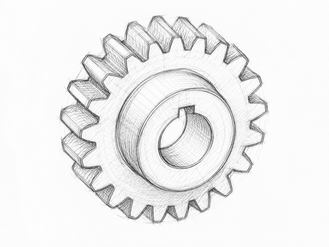
Part templatesCreate a dimensioned CAD-style technical drawing of a 24-tooth external involute spur gear, module 2.5, 20-degree pressure angle, 20 mm face width, and 12 mm finished bore. Add a 30 mm diameter raised hub with a standard parallel keyway. Show the pitch circle, tooth callout, front view, axial section, and isometric view.
 Part templates
Create a dimensioned CAD-style drawing of a 32-tooth right-hand helical gear, normal module 1.5, 20-degree pressure angle, 20-degree helix angle, 18 mm face width, and 10 mm bore. Include an integral split clamp hub with an M4 radial screw. Show helix direction, pitch diameter, section view, and isometric view.
Part templatesCreate a dimensioned CAD-style technical drawing of a 16-tooth straight bevel pinion, module 2, 45-degree pitch cone, 16 mm face width, and 15 mm keyed bore. Include a tapered web and raised rear hub. Show pitch-cone construction, axial section, front view, and isometric view.
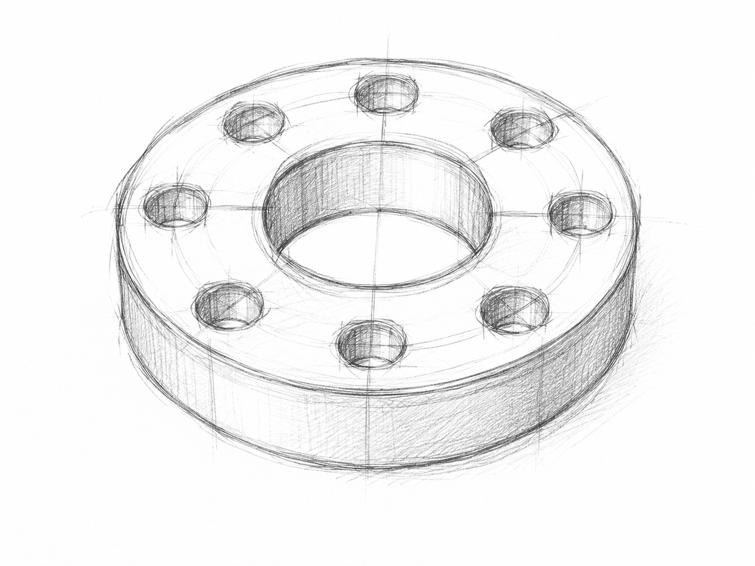
Part templatesCreate a dimensioned CAD-style technical drawing of a circular raised-face pipe flange with 120 mm outside diameter, 55 mm through bore, 16 mm body thickness, and a 3 mm high raised face. Add six equally spaced 11 mm holes on a 90 mm bolt-circle diameter. Show front, axial section, and isometric views with diameter, thickness, and angular-spacing callouts.
 Part templates
Create a dimensioned CAD-style drawing of a weld-neck flange with 200 mm outside diameter, 80 mm bore, 24 mm flange thickness, tapered hub, and raised sealing face. Add eight equally spaced 18 mm holes on a 160 mm bolt circle. Show a detailed axial half-section, front view, and isometric view with hub transition radii.
Part templatesCreate a dimensioned CAD-style technical drawing of a circular motor pilot flange with 140 mm outside diameter, 60 mm bore, and 18 mm thickness. Include a 95 mm diameter locating pilot, 4 mm deep recess, and four 9 mm holes on a 115 mm bolt circle. Show front, section, and isometric views with concentricity-oriented datums.
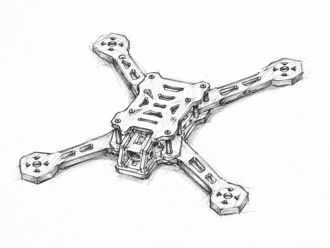
Part templatesCreate a dimensioned CAD-style drawing of a 225 mm true-X five-inch racing quadcopter frame. Use separate 5 mm carbon-fiber arms, 2.5 mm top and bottom plates, 19 by 19 mm M3 motor patterns, and concentric 20 and 30.5 mm electronics stack holes. Add camera side plates, battery-strap slots, antenna mounts, and cable reliefs. Show top, assembled isometric, and exploded views.
 Part templates
Create a dimensioned CAD-style technical drawing of a 330 mm deadcat quadcopter frame with swept front arms, replaceable 5 mm carbon-fiber arms, 3 mm center plates, 25 by 25 mm M3 motor patterns, and a vibration-isolated front camera plate. Include battery rails, GPS mast holes, cable channels, and propeller-envelope construction circles in the top view.
Part templatesCreate a dimensioned CAD-style drawing of a 900 mm radial hexacopter frame using six 25 mm carbon-fiber tubes clamped between twin 3 mm aluminum center plates. Use split boom motor clamps, a 30.5 mm avionics stack, vibration-isolated payload plate, landing-gear sockets, and routed motor-wire channels. Show top, axial stack detail, and exploded isometric views.
Part templatesCreate a dimensioned CAD-style product drawing of a foldable machined-aluminum phone stand for devices up to 82 mm wide and 13 mm thick. Use a friction hinge adjustable around a 65-degree viewing position, a 16 mm deep cradle lip, centered bottom charging slot, silicone pads, and a fold-flat base. Show open, folded, side-section, and exploded hinge views.
Part templatesCreate a dimensioned CAD-style product drawing of a weighted anodized-aluminum phone stand for devices up to 88 mm wide. Set a fixed 60-degree viewing angle, recessed wireless charging puck in the backrest, concealed cable channel through the stem, 120 by 85 mm weighted base, and full rubber base pad. Show front, side section, rear, and isometric views.
Part templatesCreate a dimensioned CAD-style assembly drawing of an articulated desk-clamp phone holder for devices up to 95 mm wide. Include a padded screw clamp for 15 to 55 mm desk thickness, two-link arm, locking ball joint, spring-loaded cradle, side cable clips, and 70-degree nominal viewing angle. Show assembled, exploded, and joint-detail views with motion arcs.
Part templatesCreate a dimensioned CAD-style technical drawing of a two-piece ABS electronics enclosure, 120 by 80 by 35 mm, with 2.5 mm nominal walls. Include four reinforced PCB bosses, a recessed lid with four captive screws, two banks of louvered side vents, a USB-C cutout, and internal corner ribs. Show exploded, axial section, underside, and isometric views.
Part templatesCreate a dimensioned CAD-style drawing of a wall-mounted outdoor sensor enclosure, 180 by 120 by 65 mm, with 3 mm walls, a continuous perimeter gasket groove, eight captive lid screws, drip edge, two M20 cable-gland bosses, and four internal PCB bosses. Include mounting tabs and show exploded, gasket-section, rear, and isometric views without open ventilation slots.
Part templatesCreate a dimensioned CAD-style technical drawing of a DIN-rail controller enclosure, 100 by 45 by 115 mm, with 2 mm walls, rear 35 mm rail clip, internal PCB card guides, removable terminal covers, bottom intake slots, top exhaust slots, and four serviceable snap hooks. Show front, side section, rear, and exploded isometric views.
Part templatesCreate a dimensioned CAD-style assembly drawing of a bench drill jig for a 120 by 60 by 20 mm aluminum plate. Use 3-2-1 locating with three rest pads, two side pins, and one adjustable end stop; add two replaceable hardened drill bushings and two vertical toggle clamps above the supports. Mount the machined aluminum base through four bench holes. Show the loaded state, exploded view, bushing section, and datum labels.
Part templatesCreate a dimensioned CAD-style fixture drawing of paired CNC vise soft jaws holding a 95 by 55 by 28 mm contoured aluminum workpiece. Machine mirrored profile nests with 3 mm relief below datum A, one end stop controlling datum C, mounting counterbores, and generous cutter access around the upper profile. Show vise interface, clamped workpiece, jaw section, and exploded isometric views.
Part templatesCreate a dimensioned CAD-style assembly drawing of a modular welding fixture for two 40 mm diameter steel tubes meeting at 90 degrees. Use adjustable V-block supports, one axial end stop, horizontal toggle clamps, copper-backed weld-clearance zones, and a slotted stress-relieved steel base plate mounted to a modular hole grid. Show loaded, open, top, and exploded isometric views with torch-access envelopes.
Part templatesCreate a dimensioned CAD-style technical drawing of an extruded aluminum heatsink with a 120 mm by 80 mm base and a 6 mm base plate. Show 21 straight fins 30 mm tall and 1.5 mm thick on a 5.5 mm pitch, 1 degree fin draft, four M4 corner clearance holes with 8 mm edge distance, and axial-fan airflow arrows along the channels. Provide front, end, and isometric views with fin pitch, fin height, and base thickness dimensioned.
Part templatesCreate a dimensioned CAD-style technical drawing of a pin-fin heatsink with a 60 mm square base and a 4 mm base plate. Show an 11 by 11 grid of 3 mm round pins 25 mm tall on a 5 mm pitch, 0.5 mm chamfered base edges, and a four-hole push-pin pattern on a 58 mm square. Provide a top view with grid pitch dimensioned, an end view, and an isometric view.
Part templatesCreate a dimensioned CAD-style section drawing of a bonded-fin heatsink, 150 mm by 100 mm with a 8 mm copper base. Show 2 mm fin roots seated in 3 mm base grooves with 1 mm root fillets, a 40 mm component contact pad, and two 8 mm heat pipes swaged into the base and routed into the fin stack. Use section hatching, leader dimensions for base thickness, groove depth, and heat-pipe centerlines.
Part templatesCreate a dimensioned CAD-style technical drawing of a steel butt hinge with two 75 mm by 30 mm leaves at 2.5 mm plate thickness. Show five knuckles on a 6 mm pin, four countersunk 4.5 mm screw holes per leaf on a 20 mm pitch, and rolled knuckle ends. Draw it closed and flat with leaf length, leaf width, knuckle length, pin diameter, and hole spacing dimensioned.
Part templatesCreate a dimensioned CAD-style technical drawing showing one 100 mm by 35 mm friction hinge twice: closed flat at 0 degrees and opened to 110 degrees. Use 3 mm leaves, three knuckles on an 8 mm pin with a torque bushing, and three staggered 4 mm countersunk holes per leaf. Mark the pin axis, annotate the swing arc and detent position, and dimension the leaf overlap and open envelope.
Part templatesCreate a dimensioned CAD-style drawing of a concealed European cabinet hinge with a 35 mm cup bored to 12.5 mm depth, a cross mounting plate, a four-bar linkage arm, and depth and overlay adjustment screws. Show a section view through the cup with the cup-to-edge distance, door thickness, and overlay dimensioned, plus an isometric view of the assembled hinge opened to 110 degrees.
Part templatesCreate a dimensioned CAD-style technical drawing of a 250 mm adjustable wrench with a 30 mm maximum jaw capacity. Show the fixed upper jaw, the sliding lower jaw riding on a rack, the worm-screw thumbwheel, a 15 degree head offset, and a knurled round handle with a lanyard hole. Provide a flat plan view with overall length and jaw capacity dimensioned, plus an enlarged head detail showing the rack and worm engagement.
Part templatesCreate a dimensioned CAD-style technical drawing of a 13 mm combination wrench, 175 mm overall length. Show a 15 degree offset open end, a 12-point box end cranked 15 degrees out of the shank plane, and a forged I-beam shank tapering toward both heads. Provide a flat plan view and a side elevation with the offset angle, overall length, and both across-flats callouts dimensioned.
Part templatesCreate a dimensioned CAD-style technical drawing of a long-arm ball-end hex key set in 2, 2.5, 3, 4, 5, and 6 mm across-flats sizes. Show the 90 degree bend, a ball end on the long arm and a chamfered plain end on the short arm, and plain hardened hexagonal bar stock. Lay the six keys out in ascending size order with each size labeled and the short-arm and long-arm lengths dimensioned on the 6 mm key.
Part templatesCreate a dimensioned CAD-style technical drawing of a swivel caster with a 100 mm polyurethane wheel on a cast iron core and a 32 mm tread width. Show a pressed steel fork, a double-ball kingpin race, a 40 mm swivel offset, a 105 by 85 mm top plate with four 9 mm holes on an 80 by 60 mm pattern, and 128 mm overall mounted height. Provide side, top, and isometric views with the swivel sweep circle shown in phantom line.
Part templatesCreate a dimensioned CAD-style top view of a caster mounting plate, 105 mm by 85 mm with 8 mm corner radii and 5 mm plate thickness. Show four 9 mm bolt holes on an 80 by 60 mm rectangular pattern, the kingpin boss at the plate center, and the 220 mm swivel sweep circle drawn in phantom line. Dimension plate size, hole diameter, hole pattern, corner radius, and plate thickness from a common datum corner.
Part templatesCreate a dimensioned CAD-style exploded drawing of a 125 mm swivel caster with a total-lock brake. Use a cast steel wheel with a 40 mm tread, a threaded stem mount, and a foot pedal that presses a shoe onto the tread while a pawl engages the swivel race. Label the axle, roller bearing, thrust washers, pedal linkage, and kingpin, and show the brake both engaged and released with the pedal travel dimensioned.
Part templatesCreate a dimensioned CAD-style technical drawing of a radial inflow turbine rotor with 13 blades, 120 mm outer diameter, 45 mm hub diameter, and 2.5 mm blade thickness. Show a 20 mm shaft bore with a 6 mm parallel keyway, blade root fillets, an axial exducer, and a scalloped back face between blade roots. Provide front, rear, and isometric views with outer diameter, hub diameter, bore, keyway, and blade count dimensioned.
Part templatesCreate a CAD-style blade profile study of a single axial turbine blade section over an annotated coordinate grid. Show the leading and trailing edge radii, the camber line, a 60 mm chord length, a 32 degree inlet angle, an 18 degree outlet angle, a 2.5 mm maximum thickness, and the root fillet where the blade meets the disc. Dimension the stagger angle and label the pressure and suction surfaces.
Part templatesCreate a dimensioned CAD-style section drawing of a shrouded centrifugal impeller with 9 backward-curved blades, 180 mm outer diameter, 60 mm eye diameter, and a 25 mm shrink-fit bore. Show the front shroud and hub disc wall thicknesses, the blade height at inlet and outlet, blade root fillets, and hatched cut faces. Add a front view with the blade count and outer diameter dimensioned.
Paste it into the DrawCAD generator, swap in your own dimensions and materials, and get a CAD-style drawing back in seconds.
Open the generator